


Vine Antennas DU-1500T Differential Manual ATU USED | 12 Months Warranty
£629.00
In stock
Description
Vine Antennas DU-1500T Differential Manual ATU USED | 12 Months Warranty
Showroom Demonstration Model

FEATURES
The DU 1500T optimizes the performance of your antenna and transmitter or SWL receiver by providing adjustable impedance matching. The DU1500T also measures the Power and Standing Wave Ratio (SWR), which allows you to tune the indicted SWR to the lowest possible ratio for the selected transmit frequency.
SPECIFICATIONS
FRONT PANEL INDICATORS AND CONTROLS
Meter…………………………Cross needle Power and SWR meter.
CONTROLS
Input Tuning………………….Continuous rotation 4,5kV capacitor 330pF
Antenna Tuning………………Continuous rotation 4,5kV capacitor 330pF
Antenna Switch Selector………Five position ceramic switch: COAX 1, Tuned and COAX 2 Tuned and BYPASS, COAX 1 DIRECT, COAX 2 DIRECT
Power Range Switch…………..Two position: 200W/2kW
Warning: !! on 1.8MHz for SWR worse then
1:3 MAX 800W!!
REAR PANEL CONNECTORS
Coax 1……………………………SO-239 Teflon connector
Coax 2……………………………SO-239 Teflon connector
Balanced Line……………………Dual high voltage ceramic terminal
Include 4:1 balun
OTHER
Frequency Coverage………………1.8-30MHz ,continuously tunable
Power Maximum…………………1500W max 2kW
Input impedance………………….50 ohm
Output impedance…………………25-600ohm and wire 2000ohm
Dimension……
……………………H 4.7” (12cm) W 13” (33cm) x D 13” (33cm)
Weight…………………………….10 lbs. (4.5kg)
CONTROL/CONNECTORS
FRONT PANEL FUNCTIONS
- Output (Transmitter) Continously adjustable input capacitor
- POWER/SWR METER Dual needle meter displays FORWARD and REFLECTED Power in Watts. The SWR in measured where the two needles intersect on the red scale.
- INPUT (Antenna)
Continuously adjustable output capacitor.
- DIRECT-TUNED MODE SWITCH
Five-position rotary switch an output coaxial connector.
1.TUNED COAX 1 selects the COAX 1connector trough the impedace matching circuit.
2.TUNED COAX 2 selects the COAX 2
connector trough the impedance matching circuit.
3.DIRECT BYPASS selects BYPASS COAX connector bypassing the impedance matching circuit but provindingSWR, FORWARD, and REFLECTED power meter readings.
4.DIRECT COAX 1 select the COAX 1 connector bypassing the impedance matching circuit but providing SWR, FORWARD, and REFLECTED meter readings.
5.DIRECT COAX 2 selects the COAX 2 connector bypassing the impedance matching circuit but providing SWR, FORWARD, and REFLECTED meter readings.
- TUNED WIRE/BAL selects the BALLINE+COAX 1 connector through the impedance matching circuit.
5.RANGE SWITCH
Two-position switch selects the range
(200W or 2kW) of FORWARD and
REFLECTED Power displayed on the power meter.
When the METER (power range) switch 200W the FORWARD meter
Scale reads 200W full scale and the REFLECTED meter scale reads 40W full scale.
When the METER switch is on 2kW, the FORWARD meter scale reads 2kW full scale and the REFLECTED meters scale reads 400W full scale.
REAR PANEL CONNECTORS
DU1500T Rear Panel
- RF INPUT – Coaxial connector for input from SWL receiver or transmitter.
2 COAX 1 – Coaxial connector for output to Antenna One.
- COAX 2 – Coaxial connector for output to Antenna Two.
- BYPASS – Coaxial connector for output to dummy load or third coax output.
- GROUND – Post/Wing-nut type ground connector.
6 BALANCED OUTPUT Two ceramic post for output to RF balanced twin-lead antennas.
People also looked at:
-
 SALE
SALEIcom IC-7300 HF Transceiver USED | Two Years LAMCO Select Warranty
£999.00 Add to basket Buy it Now -
 SALE
SALEKenwood TS-590SG HF/6M Transceiver USED | 12 Months Warranty
£1,099.00 Add to basket Buy it Now -
 SALE
SALEIcom FL-100 CW Filter USED | 12 Months Warranty
£99.00 Add to basket Buy it Now -
 SALE
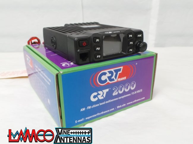
SALECRT 2000 CB Radio USED | 12 Months Warranty
£99.00 Add to basket Buy it Now -
 SALE
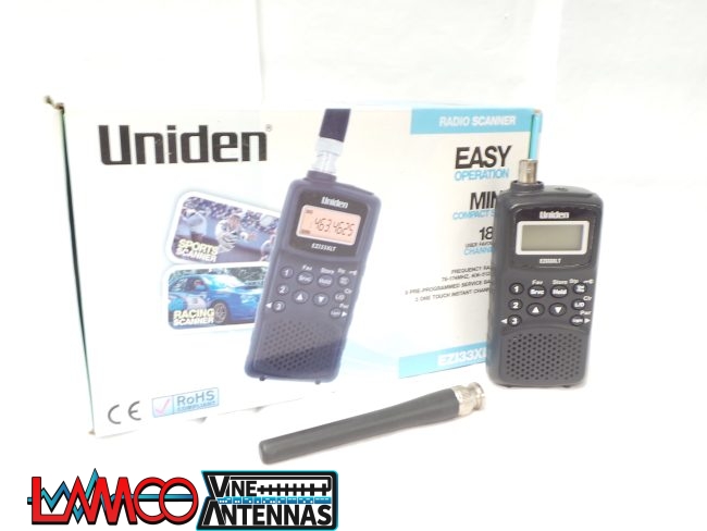
SALEUniden EZI33XLT Scanner Receiver USED | 12 Months Warranty
£69.00 Add to basket Buy it Now
