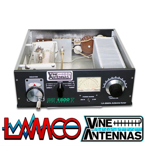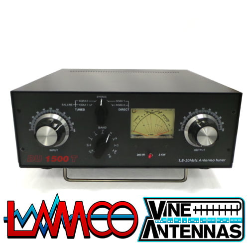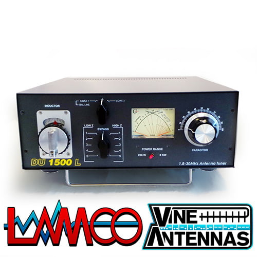
Vine Antenna DU-1500L 1.5Kw Antenna Tuner
LAMCO Barnsley
Vine Antenna DU-1500L 1.5Kw Antenna Tuner LAMCO Barnsley

EASY START GUIDE
Read all the information in the manual leading up to this point,then use the below
Instructions to start using your tuner.
Set CAPACITOR to ’2’ and INDUCTOR to fully counter-clockwise (’0’) and the center
Switch to BAYPASS.
Turn the center switch to the LOW Z 1 position (immediatly to the left of BAYPASS)
Apply 30 to 50 watts of transmitter power and note SWR show non the meter.
Unkey the transmitter and then move the switch to the HIGH Z 1 position. Apply 30 to 50
Watts or less transmitter power and note SWR show non the meter. Depending on wich of
the HIGH Z 1 or LOW Z 1 settings showed a lower SWR, try more positions on the same side to see if the SWR is lower. Choose the position among all switch position that shows lowest SWR.
Adjust the capacitor for lowest SWR. Then turn the roller inductor clockwise to a higher
setting and note if SWR changes. If SWR drops adjust the capacitor for a lower SWR
Value. Go back and forth between these two controls adjusting them for best match and the lowest available SWR.
If the capacitor shows best meter null (lowest SWR) at a setting of ’0’ turn the center switch
to the other side of BAYPASS.
If the best meter null (lowest SWR) is with the capacitor at ’100’ turn the center switch to
the next higher position.
It possible depending on your antenna and the frequency in use that a good’starting’ match may not be readily apparent (i.e. all starting positions ont he center switch show a somewhat high SWR).
Try adjusting the roller inductor and/or capacitor to a higher initial setting and repeat the
same instrictions if this the case.
WARNING:
While all the components of the DU 1500 L are rated to easly handle continuous duty
operation at full rated power, do NOT adjust the antenna tuner when runnung high
Output power. Adjust the tuner lowest SWR at less that 50 watts and then enable your
linear amplifier. High circulating currents are present when high power is applied to
the tuner adjusting the tuner controls for lower SWR while running high power through
the tuner can damage the unit.
WARNING:
In normal operation the DU 1500 L produces very high RF voltages and currents.We
do not recommend operation of this without the top cover securely installed due to the
danger of contact with high voltage.
Always be sure that a dummy load or antenna is properly connected when power is applied.
Voltages in excess of ratings can occur if no load is connected.
SPECIFICATION
FRONT PANEL INDICATORS AND CONTROLS
Meter …………………………………. Cross needle Power and SWR meter
CONTROLS
Input Tuning ………………………… Continuous rotation 4,5kV capacitor 330pF
Output Tuning ……………………… Continuous rotation 4,5kV capacitor 330pF
Antenna Switch Selector……….. Five position ceramic switch: COAX 1, Tuned and COAX 2 Tuned and BYPASS, COAX 1 DIRECT, COAX 2 DIRECT
Power Range Switch ……………. Two position: 3
00W/3kW
REAR PANEL CONNECTORS
Coax 1 ……………………………….. SO-239 Teflon connector
Coax 2 ……………………………….. SO-239 Tflon connector
Balanced Line ……………………… Dual high voltage ceramic terminal
Include 4:1 balun
OTHER
Frequency Coverage ……………. 1.8-30MHz ,continusoly tunable
Power Maximum ………………….. 3000W max 3kW
Input impedance ………………….. 50ohm
Output inoedance ………………… 25-600ohm an
d wire 2000ohm
Dimension …………………………… H 330xW
330xD 120
Weight ……………………………….. 5.5kg
CONTROL/CONNECTORS
FRONT PANEL FUNCTIONS (Refer to page 3)
- Output (Antenna)
Continously adjustable input capacitor
- POWER/SWR METER
Dual needle meter displays FORWARD and REFLECTED Power in Watts. The SWR in measured where the two needles intersecton the red scale.
- INPUT (Transmitter)
Continuously adjustable output capacitor.
- DIRECT-TUNED OUTPUT SELECTOR
Five-position rotary switch an output coaxial connector.
- TUNED COAX 1 selects the COAX 1connector trough the impedace matching circuit.
- TUNED COAX 2 selects the COAX 2 connector trough the impedance matchi circuit.
- DIRECT BYPASS selects BYPASS COAX connector by passing the
impedance matching circuit but provinding SWR, FORWARD and REFLECTED power meter readings.
- DIRECT COAX 1 select the COAX 1 connector bypassing the impedance matching circuit but providing SWR, FORWARD and REF
LECTED meter readings.
- DIRECT COAX 2 selects the COAX 2 connector bypassing the impedance matching circuit but providing SWR, FORWARD and REFLECTED meter readings.
- TUNED WIRE/BAL selects the BAL. LINE+COAX 2 connector through the impedance matching circuit.
- POWER RANGE SWITCH
Two-position switch selects the range (300W or 3kW) of FORWARD and REFLECTED Power displayed on the power meter.
When the METER (power range) switch 300W the FORWARD meter scale reads 300W full scale and the REFLECTED meter scale reads
40W full scale. When the METER switch 3kW, the FORWARD meter scale reads 3kW full scale and the REFLECTED meter scale reads 400W full scale.
- INDUCTOR Ceramic body
REAR PANEL CONNECTORS
- RF INPUT
Coaxial connector for input from SWL receiver or transmitter.
- COAX 1
Coaxial connector for output to Antenna One or Wire Antenna
- COAX 2 Coaxial connector for output to Antenna Two.
- BY PASS Coaxial connector for output to dummy load or third
coax output.
- GROUND
Post/Wing-nut type ground connector.
- BALANCED OUTPUT
Two feed through ceramic posts for output to RF balanced twin-lead antennas.
- INSTALL JUMPER – when using Balanced Output
INSTALLATION
Select a location for the DU 1500 that allows the connectors to be free of any possible contact during operation.
WARNING: SOME BALANCED OR END-FED ANTENNAS WILL PRODUCE HIGH RF VOLTAGES AT THE FEEDTHROUGH CONNECTORS. RF BURNS MAY RESULT IF TOUCHED DURING TRANSMISSION.
INSTALLATION PROCEDURES
- Connect a coax cable from your transmitter or receiver to the RF INPUT connector on the rear panel. Keep the cable as short as possible. If you use a linear amplifier, connect your transmitter to the linear amplifier output to the DU 3000.
- Connect coax cable(s) from your antenna to COAX 1 or COAX 2 connectors on the rear panel.These connectors are either direct from the transmitter or trough the tuned circuit depending on the setting of the OUTPUT SELECTOR switch on the front panel.
- If you are using a balanced feed antenna, connect the INSTALL JUMPER in the COAX 1 connector and switch band switch TUNED COAX 1.
- If using a single wire antenna, connect it to post COAX 1 without installing jumper.
- Connect a dummy load to the BYPASS CONNECTOR using a coax cable.
This lets you select the dummy load from the OUTPUT SELECTOR switch. Any antenna that does not require the use or fan antenna tuner may be connected to the BYPASS connector, if desired.
BEFORE OPERATION
- To avoid possible damage to the DU 1500, set INPUT, OUTPUT, BAND SWITCH and POWER RANGE switches as outlined in the next section before applying transmitter power.(Tuning Section)
- Begin tuning with your transmitter set to a low power setting (~50 w is more than enough)
WARNING: DO NOT OPERATE THE DU 3000 WITH THE COVER
OFF!
NOTES
- An SWR or 1:1 is best, but an SWR as high as 2:1may be acceptable. Check you transmitter manual for details.
- If you cannot get an acceptable SWR, lengthen or shorten you antenna and/or feedlines and retune.
- If you get low SWR readings at more than one setting,use the setting that:
Gives the highest FORWARD power reading.
Gives the lowest REFLECTED power reading.
Uses the largest capacitance (highest number) on the TRANSMITTER and ANTENNA controls.
- Any time a new or different antenna is connected, it is necessary to repeat the tuning procedure for each antenna.
OPERATION INSTRUCTIONS
The followings set of instructions will allow the operator to quickly place the DU 1500 L into
operation.Included are descriptions of the fromt panel controls and their functions.
This is followeed by instructions for antenna matching and selection,and a brief discourse on antenna systems matching thery.
(1)CAPACITOR
This control connects to tje variable tunung capacitor used as one of the elements in the
L type matching network.This capacitor has a tuning range of 40-500pF and is continuous tuning with no stops.
(2)INDUCTOR
This control is connected to the roller inductor,another element int he L type matching network.This inductor has a tuning range of 0,2-18uH which is coveredin approximately
30 revolutions of the control knob.A gear reduction system behind the front panel of the
DU 1500 L is connected to a concentric skirt turns counter numbered 0-29 in 180 degree
Arc over the top of this control,to make returning to earlier settings easier and quicker.
(3)IMPEDANCE SWITCH
This 11 position rotary switch is used to change the configuration of tuning network
For matching eitherhigh or low impedance antenna systems.This switch also selects
Additional capacitors as needed for matching at lower frequencies.When placed in the
12o’clock position,the tuner is connected to the BYPASS configuration and the
network has on effect ont he transmission line systems(antennas are fed through directly from the transmitter to the antenna without use of the tuner.)The SWR and power metering remains usable even when this switch is set to BAYPASS.
The purpose of this switch is to set the capacitor either across the input or across the antenna,
Depending on whether a load of above or below 50 ohms is trying to be matched(reverses the
L network).
(4)ANTENNASELECT KNOB
This 3 position switch is used to select one of up to four antennas conected to the rear panel
Of the DU 1500 L and correspond to theCOAX1,COAX2,COAX3 connectors.
(5)METER
The meter on model DU 1500 L dual crossneedle SWR and wattmeter.
Forward power output ismeasured on the right-hand needle,left-hand scale.
Reflected power is read on the left-hand needle,right-hand scale. SWR is read
by reading the point at which the two needles cross on the red scale lines on the
face of the meter.
Power output is read in switchable scales of 200 or 2000 watts.
(6)POWER RANGE SWITCH
The power scale switch is used to set the power output metering to scales of either
200 or 2000 watts.
CHAPTER 3
SPECIFICATIONS
Circuit Type: L network
RF Power Rating: 2000 watts
Frequency Range:1.8-30MHz continuous
Input Impedance: 50 ohm nominal
Output Matching Range: At least 10:1 SWR,any phase angle.
Input/Output Connectors:Input and four antenna coax connectors
Are SO-239,UHF type.Studs with wing nuts for single wire and
Balanced feeders.
Capacitor Voltage Rating: 3500 volts
Inductor: 0.2-18 uH silver-plated roller inductor.
Size: H12 x W33 x D33 cm Depth measurement cabinet only,
Does not account for knobs or connectors.
Weight: 5.5 kg
https://www.hamradio-shop.co.uk/product/vine-antenna-rs-hf-osf-80/
https://www.hamradio-shop.co.uk/product/vine-antenna-rs-hf-ocf-40/